Tuesday

WEEK 10- FYP 2

26/4/2017

Activity: 1. Find new driver for stepper motor.
         

Objective: 1. To find the suitable driver that can drive motor with high current and power.
               

Procedure:
Do some researches about the MOSFET. The Metal Oxide Semiconductor Field Effect Transistor (MOSFET, MOS-FET) is a type of field effect transistor (FET). It has an insulated gated, whose voltage determines the conductivity of the device. MOSFET provides high current and high speed for efficient switching conversion in ac-to-dc and isolated dc-to-dc converters. The MOSFET will provide enough voltages to fully turn on in the very short time. besides that, MOSFET has low impedance as low as 7 ohm.

Results/analysis:
Based on the researches about MOSFET, it can be divided into two types; Depletion mode and Enhancement mode. 

DEPLETION MODE- where is zero voltage on the gate terminal, the channel shows its maximum conductance. The channel conductivity is decreases as thevoltage on the gate is negative orpositive.
Figure 1: Depletion mode

ENHANCEMENT MODE- where there is no voltage on the gate terminal the device does not conduct. Mpre volatge applied on the gate terminal,the device has good conductivity.

Figure 2 : Enhancement mode


Monday

WEEK 9-FYP 2

19/4/2017

Activity: 1. Update the blog
                2.  Continue trobuleshoot the motor circuit

Objective: 1. Update and make some correction in certain part of this blog
                   2. To test the functionality of the circuit


Procedure:
                  1. Correcting the connection of wire leads but the IC driver become hot.
                  2. The input supply voltage of stepper motor is 12V and the common voltage (pin 16) for L293D is 5V. You can refer the pinout of the L293D as figure below


Figure 1: The pin out of L293D


Results/analysis
The maximum output current of L293D is 600mA but the current motor is 1.5A.
The L293D cannot drive the motor because the motor has high current which is 1.5A. The L293D is not suitable for this stepper motor that has been use in this project.

Conclusions
A new driver should be find to replace the driver. The new driver must have higher current to driver the motor. If the driver is low current, so that the motor can't move because it has not enough power to moves.


WEEK 8-FYP2

12/4/2017

Activity: 1.Construct the circuit on the breadboard to testing the stepper motor interface with driver
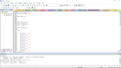
                2. Write the coding for motor and troubleshoot the error during writing the coding


Objective:  1. To ensure the motor is functioning well and can interface with the microcontroller
                    2. To write the coding for the motor movement using Keil UVision

Procedure :

                     1. Construct the simple circuit on the bread board
                     2. Compile the coding and burn it into the AT89S52 chip


The video above shows the testing of the stepper motor with L293D . The movement of motor is back and forth.

 Results/analysis: 

 The motor movement is back and forth because of the wrong leads connections. If the leads between A1, A2,B1 and B2 is wrongly placed, the stepper motor is not move sequence as follow by the coding that has been setup.

 Conclusions:
Troubleshoot the coding and check the right leads for A1,A2, B1 and B2

Friday

WEEK 7-FYP2

7/4/17

Activity: 3rd briefing of FYP2

Objective: Briefing is focusing on workshop for Methodology and Results & Discussion Writing for FYP Report presented by Dr. Kanendra Naidu.

Procedure:
                      1. Dr Kanendra Naidu give a workshop about how do the methodology, results and      discussions in the right way.
                      2. The briefing start at 3pm-5pm at TTL1


Analysis/Results:
  1. The methodology consists of: 
  • introduction
  • schematic diagram
  • block diagram
  • flow chart
  • pseucode
  • simulation block diagram
  • verification
    2. The results and discussion based on our result. 

Conclusion:
Get the clearer view how to do the better results and discussions


Thursday

WEEK 6-FYP2

29/3/2017

Activity:   1. Buy stepper motor and other components at Pasar Road.
                 3. Identify the wires/leads of stepper motor
                 2. Start write the coding for this project using KEIL

Objective:  1. To identify the mode of stepper whether unipolar or bipolar motor
                   2. To start run the coding and test the coding

Procedure :

1. Go to Pasar Road and buy the components.


                                                  Figure 1: buy a components at Electronics shop


2. Identify the wires/leads of stepper motor
Figure 2:


As figure 2 show above, we can know the pairing by see the colours of wire. But still, we can simple check using multimeter to identify which is in the same winding.

Figure 3: measure the resistance of the coil

Figure 3 show high (infinite) resistance because the black and blue wire are not part of the same coil.

Figure 4: measure thre resistance of  another coil

As we can see the figure 4, the multimeter show resistance is 39.2 Ohms. So that, red and blue wire are in the same coil.

3. Other activity for this week is run the coding of stepper motor.
Figure 5: write a coding using Keil and run it using Proteus


Analysis/ Discussion:

Based on the testing by using multimeter, the stepper motor is bipolar mode. The bipolar motor has 2 phase and 4 wires.The stepper motor voltage output is 12V. The motor driver that I used is TB6560 to drive the stepper motor.
For the sofware, I run the stepper motor coding and I found that the coding have a error. The error is because I'm not declare the port that I used for stepper motor in Keil. After that, I correcting the error and the coding is running well when run at Proteus.


Conclusion:
They are two types of stepper motor which is unipolar and bipolar. Unipolar has 5,6,8 wires while bipolar has 4 wires only. The half drive stepper motor coding is running well but I still need to modified the coding to interface with other coding after this. 


Saturday

WEEK 5 - FYP2

22/3/2017

Activity: Workshop on Introduction & Literature Review Writing

Objective:

  •      To give students understanding about their project
  •       To give students understand the correct ways of writing a solid introduction and literature review chapters in FYP final report
Content/procedure

Purpose of having chapter 1:
1) to supply sufficient background information
2) to allow readers to understand the overall project in brief.

Standard outline in this chapter:
1.1  Background of the Project
1.2  Problem Statement
1.3  Objectives of the Project
1.4  Significance of the Project
1.5  Scopes and Limitations of the Project
1.6  Chapter Summary


Purpose of having this chapter:
  1. To provide facts/ideas from reliable source (source with authors like conference papers or journals)
  2. To write only the relevant information of your project

Standard outline in this chapter:
  1. Based on your project story line

Conclusion
This workshop give me understanding how to do the chapter 1 and chapter in correct ways.

WEEK 4-FYP2

15/3/2017


Activity:  Find the component and mechanical items that will use to develop the project

Objective:  To make sure the components and mechanical items that has chosen is suitable for this project

Content/procedure:

    1. Search information's on the internet about the component such as stepper motor, LCD 20x4, microcontroller unit, push button, silicon tube and small others part.
   
STEPPER MOTOR (HYBRID SERIES)


Figure 1: L shape motor bracket
Figure 2: Hybrid stepper series


Features
  • Two phase 4 lead wires bipolar stepper
  • Hybrid stepper series
  • High torque
  • 1.8 degrees-per-step
  • single shaft
  • wire with XH 4 pin connector

Specifications
  • Model: 23HD5625-P4-8D
  • No. of Phase: 2
  • Lead Wires: 4
  • Step Angle Accuracy: ±5%(Full step, no load)
  • Speed: Various Speed (Low speed)
  • Motor Depth: 56mm
  • Step Angle: 1.8 Degree
  • Rated Current 2.8A
  • Rated Voltage: 12V - 24V DC
  • Holding Torque: 1.26N.m
  • Shaft Radial force: 10Kg/cm
  • Shaft: 8mm round shaft
  • Wire length: 30cm
  • Frame size: 56mm x 56mm 
Graphic LCD 128x64 Pixel Yellow Backlight Parallel Interface Display Module 12864B V2.0
Figure 3: LCD display 20 x 4


Features:
  • LCD display module with yellow blacklight
  • Wide viewing angle and high contrast
  • Display construction:128 x 64 DOTS (128x64 = 1024) pixels.
  • Easily interfaced with a MCU
  • Low-power consumption

Specification:
  • Number of Characters: 20 characters x 4 line
  • Input Voltage Range: DC 4.5V to 5.5V
  • Operation Voltage for LCD: 5V DC
  • Interface: 6800 8-bit Parallel
  • Display type:Positive Tranflective
  • Backlight:LED Yellow / 5.0V
  • Driving method:1/64 duty, 1/9 bias
  • Viewable area: 55 x 27.5mm
  • Module Size: 93 x 70mm
  • Weight: 70g
A minimum system board ATMEL with USB ISP
Figure 4: Minimum system board Atmel


Figure 5: Pin descriptions of AT89S52 

The AT89S52 is a low-power, high-performance CMOS 8-bit microcontroller with 8K bytes of in-system programmable Flash memory. The device is manufactured using Atmel’s high-density non-volatile memory technology and is compatible with the industry-standard 80C51 instruction set and pinout. The on-chip Flash allows the program memory to be reprogrammed in-system or by a conventional non-volatile memory programmer. By combining a versatile 8-bit CPU with in-system programmable Flash on a monolithic chip, the Atmel AT89S52 is a powerful microcontroller which provides a highly-flexible and cost effective solution to many embedded control applications.

Results/analysis


To develop this project, I decided to use LCD display 20 x 4 because it will be easy to interface with the microcontroller instead of using 2 LCD 16 x 4 . Moreover, if I use 2 LCD  16 x 2 display, it will be like complicated and the i/o AT8S52 is not enough . for the microcontroller, I choose to use AT89S52.

Conclusion

For this project, the input will be the fluid with waste product that will flow along the silicone tube that will control by the peristaltic pump 1 (stepper motor 1). The LCD display will display each process during the treatment. The fluid with waste product will flow into the water filter and the water filter will trapped the waste product (microbeads). After filtration process, the clean fluid (output) will return to the bag/beaker.