Activity: 1. Buy stepper motor and other components at Pasar Road.
3. Identify the wires/leads of stepper motor
2. Start write the coding for this project using KEIL
Objective: 1. To identify the mode of stepper whether unipolar or bipolar motor
2. To start run the coding and test the coding
Procedure :
1. Go to Pasar Road and buy the components.
Figure 1: buy a components at Electronics shop
2. Identify the wires/leads of stepper motor
 |
| Figure 2: |
As figure 2 show above, we can know the pairing by see the colours of wire. But still, we can simple check using multimeter to identify which is in the same winding.
 |
Figure 3: measure the resistance of the coil
|
Figure 3 show high (infinite) resistance because the black and blue wire are not part of the same coil.
 |
| Figure 4: measure thre resistance of another coil |
As we can see the figure 4, the multimeter show resistance is 39.2 Ohms. So that, red and blue wire are in the same coil.
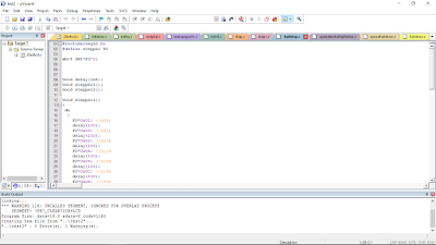
3. Other activity for this week is run the coding of stepper motor.
 |
Figure 5: write a coding using Keil and run it using Proteus
|
Analysis/ Discussion:
Based on the testing by using multimeter, the stepper motor is bipolar mode. The bipolar motor has 2 phase and 4 wires.The stepper motor voltage output is 12V. The motor driver that I used is TB6560 to drive the stepper motor.
For the sofware, I run the stepper motor coding and I found that the coding have a error. The error is because I'm not declare the port that I used for stepper motor in Keil. After that, I correcting the error and the coding is running well when run at Proteus.
For the sofware, I run the stepper motor coding and I found that the coding have a error. The error is because I'm not declare the port that I used for stepper motor in Keil. After that, I correcting the error and the coding is running well when run at Proteus.
Conclusion:
They are two types of stepper motor which is unipolar and bipolar. Unipolar has 5,6,8 wires while bipolar has 4 wires only. The half drive stepper motor coding is running well but I still need to modified the coding to interface with other coding after this.
They are two types of stepper motor which is unipolar and bipolar. Unipolar has 5,6,8 wires while bipolar has 4 wires only. The half drive stepper motor coding is running well but I still need to modified the coding to interface with other coding after this.

No comments:
Post a Comment