Thursday

WEEK 6-FYP2

29/3/2017

Activity:   1. Buy stepper motor and other components at Pasar Road.
                 3. Identify the wires/leads of stepper motor
                 2. Start write the coding for this project using KEIL

Objective:  1. To identify the mode of stepper whether unipolar or bipolar motor
                   2. To start run the coding and test the coding

Procedure :

1. Go to Pasar Road and buy the components.


                                                  Figure 1: buy a components at Electronics shop


2. Identify the wires/leads of stepper motor
Figure 2:


As figure 2 show above, we can know the pairing by see the colours of wire. But still, we can simple check using multimeter to identify which is in the same winding.

Figure 3: measure the resistance of the coil

Figure 3 show high (infinite) resistance because the black and blue wire are not part of the same coil.

Figure 4: measure thre resistance of  another coil

As we can see the figure 4, the multimeter show resistance is 39.2 Ohms. So that, red and blue wire are in the same coil.

3. Other activity for this week is run the coding of stepper motor.
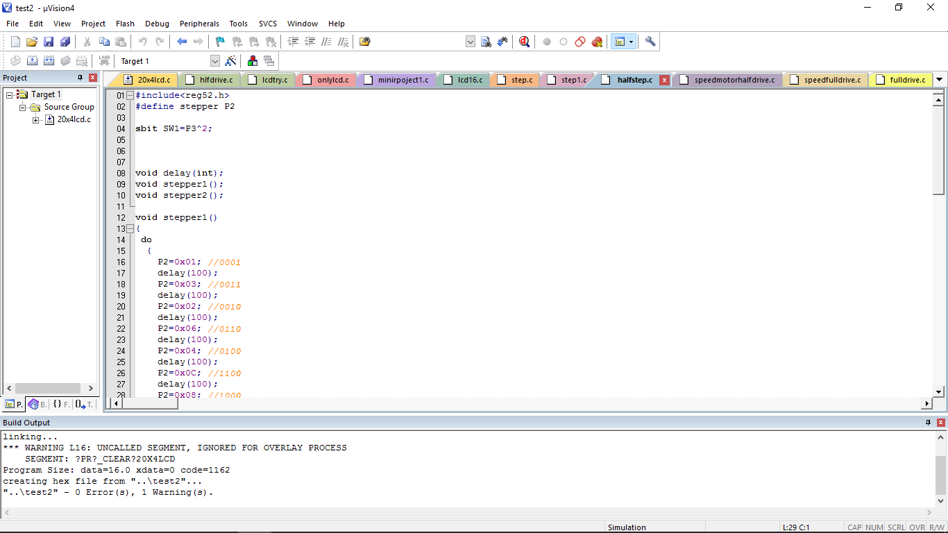
Figure 5: write a coding using Keil and run it using Proteus


Analysis/ Discussion:

Based on the testing by using multimeter, the stepper motor is bipolar mode. The bipolar motor has 2 phase and 4 wires.The stepper motor voltage output is 12V. The motor driver that I used is TB6560 to drive the stepper motor.
For the sofware, I run the stepper motor coding and I found that the coding have a error. The error is because I'm not declare the port that I used for stepper motor in Keil. After that, I correcting the error and the coding is running well when run at Proteus.


Conclusion:
They are two types of stepper motor which is unipolar and bipolar. Unipolar has 5,6,8 wires while bipolar has 4 wires only. The half drive stepper motor coding is running well but I still need to modified the coding to interface with other coding after this. 


Saturday

WEEK 5 - FYP2

22/3/2017

Activity: Workshop on Introduction & Literature Review Writing

Objective:

  •      To give students understanding about their project
  •       To give students understand the correct ways of writing a solid introduction and literature review chapters in FYP final report
Content/procedure

Purpose of having chapter 1:
1) to supply sufficient background information
2) to allow readers to understand the overall project in brief.

Standard outline in this chapter:
1.1  Background of the Project
1.2  Problem Statement
1.3  Objectives of the Project
1.4  Significance of the Project
1.5  Scopes and Limitations of the Project
1.6  Chapter Summary


Purpose of having this chapter:
  1. To provide facts/ideas from reliable source (source with authors like conference papers or journals)
  2. To write only the relevant information of your project

Standard outline in this chapter:
  1. Based on your project story line

Conclusion
This workshop give me understanding how to do the chapter 1 and chapter in correct ways.

WEEK 4-FYP2

15/3/2017


Activity:  Find the component and mechanical items that will use to develop the project

Objective:  To make sure the components and mechanical items that has chosen is suitable for this project

Content/procedure:

    1. Search information's on the internet about the component such as stepper motor, LCD 20x4, microcontroller unit, push button, silicon tube and small others part.
   
STEPPER MOTOR (HYBRID SERIES)


Figure 1: L shape motor bracket
Figure 2: Hybrid stepper series


Features
  • Two phase 4 lead wires bipolar stepper
  • Hybrid stepper series
  • High torque
  • 1.8 degrees-per-step
  • single shaft
  • wire with XH 4 pin connector

Specifications
  • Model: 23HD5625-P4-8D
  • No. of Phase: 2
  • Lead Wires: 4
  • Step Angle Accuracy: ±5%(Full step, no load)
  • Speed: Various Speed (Low speed)
  • Motor Depth: 56mm
  • Step Angle: 1.8 Degree
  • Rated Current 2.8A
  • Rated Voltage: 12V - 24V DC
  • Holding Torque: 1.26N.m
  • Shaft Radial force: 10Kg/cm
  • Shaft: 8mm round shaft
  • Wire length: 30cm
  • Frame size: 56mm x 56mm 
Graphic LCD 128x64 Pixel Yellow Backlight Parallel Interface Display Module 12864B V2.0
Figure 3: LCD display 20 x 4


Features:
  • LCD display module with yellow blacklight
  • Wide viewing angle and high contrast
  • Display construction:128 x 64 DOTS (128x64 = 1024) pixels.
  • Easily interfaced with a MCU
  • Low-power consumption

Specification:
  • Number of Characters: 20 characters x 4 line
  • Input Voltage Range: DC 4.5V to 5.5V
  • Operation Voltage for LCD: 5V DC
  • Interface: 6800 8-bit Parallel
  • Display type:Positive Tranflective
  • Backlight:LED Yellow / 5.0V
  • Driving method:1/64 duty, 1/9 bias
  • Viewable area: 55 x 27.5mm
  • Module Size: 93 x 70mm
  • Weight: 70g
A minimum system board ATMEL with USB ISP
Figure 4: Minimum system board Atmel


Figure 5: Pin descriptions of AT89S52 

The AT89S52 is a low-power, high-performance CMOS 8-bit microcontroller with 8K bytes of in-system programmable Flash memory. The device is manufactured using Atmel’s high-density non-volatile memory technology and is compatible with the industry-standard 80C51 instruction set and pinout. The on-chip Flash allows the program memory to be reprogrammed in-system or by a conventional non-volatile memory programmer. By combining a versatile 8-bit CPU with in-system programmable Flash on a monolithic chip, the Atmel AT89S52 is a powerful microcontroller which provides a highly-flexible and cost effective solution to many embedded control applications.

Results/analysis


To develop this project, I decided to use LCD display 20 x 4 because it will be easy to interface with the microcontroller instead of using 2 LCD 16 x 4 . Moreover, if I use 2 LCD  16 x 2 display, it will be like complicated and the i/o AT8S52 is not enough . for the microcontroller, I choose to use AT89S52.

Conclusion

For this project, the input will be the fluid with waste product that will flow along the silicone tube that will control by the peristaltic pump 1 (stepper motor 1). The LCD display will display each process during the treatment. The fluid with waste product will flow into the water filter and the water filter will trapped the waste product (microbeads). After filtration process, the clean fluid (output) will return to the bag/beaker. 


WEEK 3-FYP 2

8/3/2017

Activity: First FYP 2 briefing that conducting by Madam Zarith Liyana

Objective : To brief the student about the timeline of the FYP 2 (Semester 1/2017)

Content/Procedure:


  • A briefing about the project development and the progress report is briefed by the Madam Zarith Liyana
  • The timeline for the FYP 2 in this semester is explained 
  • the project development such as log book , thesis were also explained.
Conclusion

I more clear about the important dates for the whole semester and I will more alert about the important day such as workshop, report submission and so on. 


Friday

WEEK 2-FYP 2

1/3/2017

Activity:    Study and choose what controlling process of the dialyser that suit with my project.

Objective: To know more about the dialyser which is the main part in hemodialysis treatment.

Content/procedure:

Diffusion is the exchange of things dissolved in fluid (solutes) across the membrane due to differences in the amounts of the solutes on the two sides (concentration gradient). If there is a higher concentration of a given solute on one side of the membrane than on the other, then diffusion will occur to try to make the concentrations on both sides of the membrane the same. By controlling the chemicals in the dialysate, the dialysis machine controls this transfer of solutes according to the doctor's prescription. Dialysis machines control the chemicals in the dialysate by mixing dialysis fluid concentrates, which are strong versions of the chemicals, (acetate or sodium bicarbonate plus acetic acid based solutions) with purified water. The mixing is generally controlled using either conductivity control (measuring how well the fluid conducts electricity) or by volumetric control (how much water is mixed with how much chemical) of the water and concentrates. Sodium profiling (changing the amount of sodium in the dialysis fluid at various times during the treatment) is used in many modern dialysis machines to vary the conductivity of the dialysate over the course of the treatment to improve the total amount of solute removed by diffusion.

Ultrafiltration, also referred to as convection, is fluid flow through the membrane, forced by a difference in pressure on the two sides of the dialyzer (pressure gradient). This controls the patient's weight loss over the course of the treatment. While earlier dialysis machines either controlled dialysate pressure or the pressure difference across the membrane in order to achieve ultrafiltration, modern dialysis machines are generally volumetric, meaning they control the volume of fluid removed from the patient directly and allowing dialysate pressure to change as it will in order to achieve the prescribed weight loss. Volumetric control is generally achieved either by controlling the flow of dialysate in and out of the dialyzer at different rates with two flow controllers, or by having equal flow rates in and out of the dialyzer and removing fluid between these equal flows. Volumetric control allows the doctor to take advantage of more effective "high flux" dialyzers, which allow a great deal of fluid movement with very little pressure differences.

   Osmosis is the net movement of water across a selectively permeable membrane driven by a difference in the amounts of solute on the two sides of the membrane. In dialysis, this refers not to water movement across the hemodialyzer membrane, but across cell membranes within the body-either from within the red cells to the blood plasma, or from within cells of the various tissues in the body (like muscles) to interstitial fluid (the fluid in between cells). Sodium profiling, as described in the "diffusion" section, can be used to increase the rate of osmosis early in the treatment by increasing the sodium level of the plasma


Result/analysis
In this project, I choose to use osmosis controlling process. Osmosis is the net movement of water across a filter. The fluid that I use is syrup water with microbeads. So that, the waste (microbeads) will trapped at the water filter.  the figures below show the stepper motor hybrid series that I bought from the QQ Trading at Pasar Road.  


Figure 1:Upfront  view of the stepper motor 
Figure 2: Side view of the stepper motor


WEEK 1-FYP2

22/2/2017

Activity: 
                 -Study more about dialyser and peristaltic pump
                 - study more about the hemodialysis


Objective:
- To more understand about the haemodialysis before develop the prototype.
- To more understand about the main part of the project which is dialyser and peristaltic pump.

Content/procedure:

The bipolar stepper motor usually has four wires coming out of it. Unlike unipolar steppers, bipolar steppers have no common center connection. They have two independent sets of coils instead. You can distinguish them from unipolar steppers by measuring the resistance between the wires. You should find two pairs of wires with equal resistance. If you've got the leads of your meter connected to two wires that are not connected (i.e. not attached to the same coil), you should see infinite resistance (or no continuity).

Figure 1: The stepper motor coils


There are two types of dialysis: hemodialysis and peritoneal dialysis. In hemodialysis, blood is passed through an artificial kidney (hemodialyzer) to clean it. Peritoneal dialysis uses a filtering process like hemodialysis, but the blood is cleaned inside the body rather than in a machine.
Peritoneal dialysis is a treatment for kidney failure that uses the lining of your abdomen, or belly, to filter the blood inside a body. Doctors call this lining the peritoneum. A doctor will place a catheter in a belly a few weeks before start the treatment.
When the peritoneal dialysis is start, dialysis solution like a water with salt and other additives will flows from a bag through the catheter into a belly. When the bag is empty, the catheter can disconnect from the bag and cap it so patient can move around and do normal activities. While the dialysis solution is inside a belly, it soaks up wastes and extra fluid from the body. After a few hours, drain the used dialysis solution into a drain bag. Patient can then dispose of the used dialysis solution, which is now full of wastes and extra fluid, in a toilet or down the drain of a sink or bathtub. Then start over with a fresh bag of dialysis solution.
In hemodialysis, blood is removed from the body and circulated through an extracorporeal fluid circuit (outside the body), then returned to the patient. This circuit includes a hemodialyzer, which is where the blood is cleaned. The hemodialyzer contains a selectively permeable membrane, which is a filter that allows fluids and waste (uremic toxins) to pass through, but prevents the exchange of blood components, microorganisms and the "skeletons" of dead microorganisms (endotoxins). The fluid used to clean the blood (dialysate) flows in the opposite direction to the blood on the opposite side of the membrane, while waste and extra fluid are removed from the blood and end up in the dialysate

Result and analysis

I has choose the hemodialysis treatment because it is most often done by trained health professionals who can watch for any problems. It allows patient to be in contact with other people having dialysis, which may give emotional support to patients. Also, patient don't have to do it by their self, as do with peritoneal dialysis. While the peritoneal can  increases the risk for an infection of the lining of the belly, called peritonitis. For the peristaltic pump, I will use stepper motor bipolar series. Bipolar motor have high torque.

Conclusion
Proceed to buying the component next week to start the design the circuit and simulating the circuit using Proteus. Also, to study about the dialyser controlling process.


Wednesday

WEEK 14

4/1/2017

Activity: Submit report proposal and complete update blog


Objective:

  1. Explain all activities done for passed 14 week for this semester
  2. Update and make some correction in certain part of this blog
  3. Submit report proposal to supervisor

Content/procedure:

  1. Send the draft or report to supervisor before submit the final report proposal
  2. Supervisor make some correction on my report
Result/analysis:

  1. Report Proposal will be submitted on 6/1/2017
  2. Blog is done updated until week 14
Conclusion:

Even though I have completed submit my proposal and my blog, I still have to prepare for my FYP 2, which is the mechanical parts for the next semester. Overall, all the tasks given for this semester had been done completely. Special thanks to my supervisor, Dr Ahmad Sabry , who always guide me to archive my objective for this semester. Thanks a lot to my family and friends that always support me doing my project.